Shopping Cart
0 item(s) - USD 0.00- 5W Resistor (6)
- Arduino Development (64)
- Audio (8)
- Batteries (17)
- Cable & Wire (36)
- Capacitors (41)
- Charger (7)
- CNC Machine (4)
- Connector (26)
- Connector (3)
- Connector & Sockets (3)
- Crystals / Oscillators (9)
- DCA Professional Power Tools (0)
- Development Tools/ Programmers (10)
- Digital Oscilloscope (0)
- Display (65)
- Domino (5)
- Driller (16)
- ECOSPARKS PRODUCTS (0)
- Electrical Products (1)
- Ferrit (1)
- GPS Module (5)
- GSM Module (8)
- Headers (15)
- Heat shrinkable tubing (7)
- IC-Driver (17)
- IC-Microcontroller (31)
- IC-OpAm (13)
- IC-Timer (5)
- Inductors SMD (0)
- Inductors/Coils/Chokes (16)
- Integrated Circuits ( ICs ) (1)
- Max Family (7)
- Micro SD (7)
- Module Bluetooth/ Bluetooth (5)
- Module Relays (6)
- MosFet & Fet (15)
- Motor Pump (4)
- Optical Sensor (11)
- Optocouplers (3)
- Other Products (1)
- Over Voltage / Current (11)
- PCB (16)
- Potentiometers / Variable Resist (16)
- Power Supply (16)
- Projects Box (1)
- Raspberry Pi (31)
- Regulators (20)
- Relays (11)
- RePair Battery LapTop (2)
- Resistor-Network (3)
- Resistors (52)
- RF IC, Module (13)
- ROBOTIC (55)
- Semiconductors (0)
- Sensors / Transducer (82)
- Service and Repare (0)
- Smart Home (2)
- Socket-IC (10)
- Solar Panel (4)
- Solder (8)
- Soldering Tool (28)
- Specialized Function IC (10)
- surface mount (SMD) (35)
- Switches, Key Pad (25)
- Terminal block (11)
- Test & Measurement (21)
- Testboard (6)
- Tools & Supplies (57)
- Transistor (32)
- Triac (3)
- USB Connector (10)
- USB to Serial (13)
- WiFi Module (13)
- Wire Termial (15)
- Diodes (20)
- IC-Logic Family (29)
Dot Matrix 8x8 (2 color)
Availability: In Stock
Add to Compare
LED Matrix 8x8 Dual Color (Red/Green) 6cm x 6cm
- Size 6cm x 6cm
- Height 9.2mm
- 8 x 8 = 64 2-Colour LED (Red + Green)
- LED Size 5mm
- 24 Pin standard-layout
For detailed technical information as well as the pin layout, please refer to the attached datasheet!
Product Attachments
![]() LNM2088BEG2C Datasheet Size: (274.19 KB)
LNM2088BEG2C Datasheet Size: (274.19 KB)
The way you actually control them is like this:
ROW ---1-2-3-4-5-6-7-8
Column-2
---------3
---------4
---------5
---------6
---------7
---------8
You have to active a + pin and a - pin to light one of the lights (say for example the 6th led in the 2nd row, you would have to activate a positive charge on pin 6(or pin that goes to that column) and a negative charge on pin 2 (or pin that goes to that row
You will have two different positive pins for each led. One for one color and one for the other, however they use the same negative line.
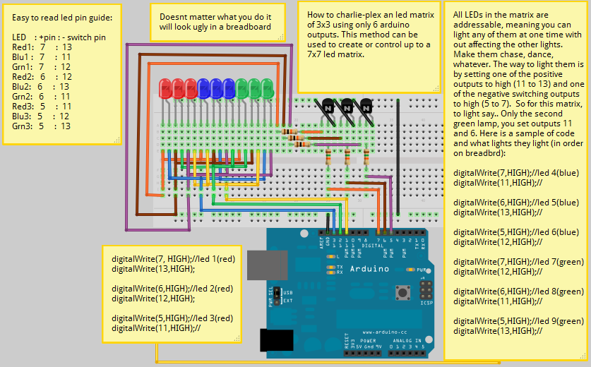
Look at my 3x3 sketch in Fritzing:

This is the way it looks on the breadboard (in fritzing) but here is what it looks like in real life (Sorta)

Now then with these two things taken into account, you know you can't switch on and off a negative port on the arduino, so to sidestep this, you use a transistor OR a chip like the MAX7219CNG or a 74HC238, but for your understanding you should consider the theory of using the transistor.
You can use a transistor as a switch, and the beautiful thing about it, is it's an indirect switch which means you can switch positive OR negative signals on or off. So what you are doing is using the transistor as a sort of "negative switch", so you can switch on any positive and/or negative pins on the led matrix that you want at any given time.
Another way you could look at it is an old school time table.

Say you needed to get to LED number 42 (dont mind that there are other numbers the same.....) you need to put a positive charge on Row 7 and a negative charge onColumn 6.
Hope that helps!
Write a review
Your Name:Your Review: Note: HTML is not translated!
Rating: Bad Good
Enter the code in the box below:
Cambodia Electronic Source © 2024


