Shopping Cart
0 item(s) - USD 0.00- 5W Resistor (6)
- Arduino Development (64)
- Audio (8)
- Batteries (17)
- Cable & Wire (36)
- Capacitors (41)
- Charger (7)
- CNC Machine (4)
- Connector (26)
- Connector (3)
- Connector & Sockets (3)
- Crystals / Oscillators (9)
- DCA Professional Power Tools (0)
- Development Tools/ Programmers (10)
- Digital Oscilloscope (0)
- Display (65)
- Domino (5)
- Driller (16)
- ECOSPARKS PRODUCTS (0)
- Electrical Products (1)
- Ferrit (1)
- GPS Module (5)
- GSM Module (8)
- Headers (15)
- Heat shrinkable tubing (7)
- IC-Driver (17)
- IC-Microcontroller (31)
- IC-OpAm (13)
- IC-Timer (5)
- Inductors SMD (0)
- Inductors/Coils/Chokes (16)
- Integrated Circuits ( ICs ) (1)
- Max Family (7)
- Micro SD (7)
- Module Bluetooth/ Bluetooth (5)
- Module Relays (6)
- MosFet & Fet (15)
- Motor Pump (4)
- Optical Sensor (11)
- Optocouplers (3)
- Other Products (1)
- Over Voltage / Current (11)
- PCB (16)
- Potentiometers / Variable Resist (16)
- Power Supply (16)
- Projects Box (1)
- Raspberry Pi (31)
- Regulators (20)
- Relays (11)
- RePair Battery LapTop (2)
- Resistor-Network (3)
- Resistors (52)
- RF IC, Module (13)
- ROBOTIC (55)
- Semiconductors (0)
- Sensors / Transducer (82)
- Service and Repare (0)
- Smart Home (2)
- Socket-IC (10)
- Solar Panel (4)
- Solder (8)
- Soldering Tool (28)
- Specialized Function IC (10)
- surface mount (SMD) (35)
- Switches, Key Pad (25)
- Terminal block (11)
- Test & Measurement (21)
- Testboard (6)
- Tools & Supplies (57)
- Transistor (32)
- Triac (3)
- USB Connector (10)
- USB to Serial (13)
- WiFi Module (13)
- Wire Termial (15)
- Diodes (20)
- IC-Logic Family (29)
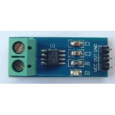
ACS 712 Hall Effect Current Sensor Module
Availability: In Stock
Add to Compare
The ACS712 Current Sensors offered on the internet are designed to be easily used with micro controllers like the Arduino.
These sensors are based on the Allegro ACS712ELC chip.
These current sensors are offered with full scale values of 5A, 20A and 30A.
The basic functional operation of each of these devices is identical. The only difference is with the scale factor at the output as detailed below.
Sensor Specifications
| 5A Module | 20A Module | 30A Module | |
|---|---|---|---|
| Supply Voltage (VCC) | 5Vdc Nominal | 5Vdc Nominal | 5Vdc Nominal |
| Measurement Range | -5 to +5 Amps | -20 to +20 Amps | -30 to +30 Amps |
| Voltage at 0A | VCC/2 (nominally 2.5Vdc) |
VCC/2 (nominally 2.5Vdc) |
VCC/2 (nominally 2.5VDC) |
| Scale Factor | 185 mV per Amp | 100 mV per Amp | 66 mV per Amp |
| Chip | ACS712ELC-05A | ACS712ELC-10A | ACS712ELC-30A |
ACS712 Module Pin Outs and Connections
The picture below identifies the pin outs for the ACS172 Modules.
Pay attention to the polarity at the load end of the device. If you are connected as illustrated below, the output will raise. If you connect it opposite of this picture, the output will decrease from the 2.5 volt offset.
 Basic Hook Up and Functional Description
As mentioned before, these modules are primarily designed for use with micro-controllers like the Arduino. In those applications, the connections would be as picture below:
If the light bulb shown in the picture above were disconnected, the output of the ACS712 module would be 2.500 volts.
Once connected, the output would be scaled to the current drawn through the bulb. If this were a 5 Amp module and the light bulb pulled 1 Amp, the output of the module would be 2.685 volts.
Now imagine the battery polarity reversed. Using the same 5A module, the output would be 2.315 volts.
IMPORTANT NOTE – This device is a Hall Effect transducer. It should not be used near significant magnetic
ACS712ELC Datasheet
The datasheet below will give you greater insight into the specifications and operation of this manual.
Write a review
Your Name:Your Review: Note: HTML is not translated!
Rating: Bad Good
Enter the code in the box below:
Cambodia Electronic Source © 2024


